Designing Instruments for Electronic Music
Held in Manchester from 24–26 October 2014, the first Sines & Squares Festival of Analogue Electronics and Modular Synthesis was an initiative of Richard Scott, Guest Editor for this issue of eContact! Some of the authors in this issue presented their work in the many concerts, conferences and master classes that comprised the festival, and articles based on those presentations are featured here. After an extremely enjoyable and successful first edition, the second edition is in planning for 18–20 November 2016. Sines & Squares 2014 was realised in collaboration with Ricardo Climent, Sam Weaver, students at NOVARS Research Centre at Manchester University and Islington Mill Studios.
In the last fifteen years the interest for sound synthesis instruments developed specifically for electronic music has grown tremendously. However, electronic music stretches across an extremely wide range, encompassing myriad styles and genres of electronic music. These genres range from the more traditional “academic” electronic music to dance music to experimental noize and drone genres, and much in between. So, to design an instrument that would be useful for all, or at least for several of the more experimental genres of electronic music, requests an open and “modular” approach. And this is surely one of the reasons why analogue modular synthesizers have become even more in fashion as they ever were in their heyday in the 1960s and 1970s.
Another development is the increase in DIY instruments for electronic music, instruments that are tailor-made by the artists who are themselves also going to play the instrument. There is a huge amount of circuitry schematics published on the Internet, and most probably all the basic information that one needs to design and build a working DIY instrument is readily available online. Still, this doesn’t mean instant success in building such an instrument. In this article the author would like to very briefly go over the different steps it takes to develop an original idea for an instrument into a completed instrument that is ready to be played.
Sound synthesis is basically a science, but music is an art. An electronic music instrument applies science to be able to create art. This means that in the design process for such an instrument one inevitably moves back and forth on a line between art and science. If one has a certain inclination towards either art or science this may actually be an issue that one has to overcome in order to let creativity flow. A helpful realisation is that art and science are both expressions of human nature and, in that sense, equally valued. With this understanding, one can freely flow back and forth between scientific research and artistic expression and be creative in both realms, as they are just the two ends of the same stick.
The design process for an instrument for electronic music goes through several stages. Each stage is equally important, as when one stage is skipped, or not proper taken care of, the chance to end up with a “well-designed” instrument decreases.
Conceptual Design
The stage to begin with is the conceptual design. In this stage one defines in general what the instrument will be used for and how it can be played, and all general requirements needed for this purpose. It makes a difference, for example, if the instrument will be used in live situations or only in a studio situation. This brings about the question of whether it is meant to be a portable instrument or will always sit in the same place, in which case size and weight don’t matter as much. Also it is necessary to define where the instrument “sits” in terms of size — it could be, on one hand, a big all-purpose wall-filling rig or, on the other hand, a small, one-trick pony gadget. Other considerations are if the instrument will be played by a keyboard, by sensors or just by its knobs. Ergonomic issues are important to consider in the conceptual stage, as such considerations can greatly affect playability. The final result should preferably feel like a real instrument that is a joy to play with. Considerations around the available budget may already predetermine the number of high-quality controls and sensors that could be used to increase playability.
The final form factor and the materials used for a case and front panels will also be considered in the conceptual stage. This includes making an inventory of the available tools and knowledge about how to use these tools on certain materials. For example, when finally building the instrument, one would most certainly need PCBs for the electronic circuitry, as well as a case with a power supply to house the PCBs and the knobs, sliders, sensors, etc. If all tools necessary to make PCBs, a case and the front panels are available, there is a lot of freedom in the conceptual design. But if one needs to rely on external services for PCBs and front panels, this may severely affect the available budget. In this case it may help to work together with others interested in the same concept to see if group buys can reduce the costs to work with external PCB and front panel services.
The main purpose of the conceptual stage is to end up with a clear and well-defined picture of all the work that needs to be done to finish the project successfully. It should also include an estimation of the costs and all the knowledge that is needed to finish the project. This last one is of special interest, as it is very well possible that not all knowledge is present at this stage. But when it is known which knowledge is not present, one can systematically seek it out. And when the missing knowledge is found, one can study it to make it one’s own. This may include doing experiments. For example, to get a better knowledge of what is going on in the electronic circuitry one may first want to make test setups on breadboards and thus try to understand what is actually going on. One might also want to do tests with certain materials, such as different approaches to making front panels by using metals, plastic or wood. Or figuring out which are the best tools and methods to drill nice round holes in a thin metal sheet. Of course, the longer one has been involved with DIY, the more experience is developed and the easier it becomes to come up with a good conceptual design.
To conclude, the conceptual design tells all about the look and feel of the instrument and how and for which purposes it can be used, but doesn’t necessarily go into detail yet about individual functions.
Functional Design
Individual functions are defined in the functional design that will follow from the conceptual design. In a modular approach it is sometimes assumed that each technical function needs to be a separate physical module. But this doesn’t have to be. It is better to think more musically about functions so that a module takes on a “musical” function instead of just a pure technical one.
One important thing to keep in mind is that the instrument, and therefore the functions, will work with electronic signals describing sound waves. There are three basic parameters that describe sound waves: pitch, amplitude and timbre. And these three parameters constantly change over time. What the functions need to be able to do, or respond to, is the control of these basic three parameters in their change over time. In essence each function performs a computation on a passing sound wave. Such a computation may be a very simple one, like multiplying the sound wave amplitude with a constant value set by a knob or fader and adding the result to another sound wave. This is what actually happens in a simple mixer; the process of mixing is nothing more than setting multiplication factors for the sound wave amplitudes before they are added together. If one would want to automate this mixing process, one could replace the static knobs and faders by control voltages and voltage-controlled amplifiers or DSP MAC instructions. This would allow the user to “modulate” the mix. And here we arrive at the real essence of an instrument for electronic music: the possibility to apply modulations, preferably to every control that affects the basic three parameters of sound waves in a function. Each modulation is in essence a computation, so it is not a bad idea to look at the operations at the functional design level as computations. This implies that what is designed is in essence a computing device, though not necessarily a digital computer.
Practically speaking, it doesn’t matter if a computation is done by analogue, digital or even by mechanical means: if the outcome of the computation is correct then it is valid and does the job. The designer is free to choose the techniques used for the computations, and any mix of techniques can be used, as long as it fits in the concept. So, this can feed back into the conceptual design. One can, for example, employ one or more mechanical devices — a string to be plucked or bowed, a reverb spring, acoustic feedback, a rotating disk with lights and sensors, etc. — in the conceptual design and look at these mechanical contraptions as simple sound wave computation functions at the functional design level.
The functional design will result in a list of all the individual sound-generating and sound-processing elements, traditionally referred to as “modules”, that will be present in the final instrument. And as said before, a module does not necessarily have to be a separate physical entity; several modules may be present behind a single panel. The list of functions needs to be a well balanced set, meaning that whatever is needed for the main purpose of the instrument should be there… and really not much more. This would be defined in the conceptual design, which, when done carefully and efficiently, will prevent a mismatch at the functional level. And this could also help maintain a healthy project budget, in the sense that no extra costs are made for functions that are of no interest for the principal intended uses of the instrument and would probably be hardly used. In the real world, the question could be: How many oscillators does one really need if there are only x amount of mixing and filtering functions available? This is where the conceptual design and the functional design link with each other.
Algorithms
A very important insight is that computations and thus computers are not really about individual bits and numbers, but rather algorithms. An algorithm is in essence the description of an effective procedure that performs a certain task. The tasks in a sound synthesizer are to perform computations on the electronic signals that describe the sound waves, with the purpose to generate new sound waves or change one or more of the three sound wave parameters of existing sound waves. Which brings us to the third design level: the algorithmic level. For each function as described in the functional design a proper algorithm must be applied. Within an algorithm one or more calculations may be necessary, and so-called conditionals or branch decisions are also quite common. The quality of the algorithms will greatly define the final sound quality. One may want to develop all algorithms oneself, but luckily many algorithms for generating and processing sound waves are readily present on the Internet and in literature. But they may also come disguised as an electronic schematic found on the Internet without further description. To understand such a schematic all one has to do is look at it as an algorithm, meaning split it in parts and analyse what the parts do and how together they implement the algorithm. In general, each part will do some calculus on a passing sound wave signal and/or take a decision of some sort.
Let’s look at an example of an algorithm for a triangle/square wave oscillator. This algorithm is commonly used for modulation signal generators like LFOs and sometimes for audio rate oscillators. The algorithm assumes that a singular storage device is available — this can be an analogue capacitor in an analogue circuit, a register containing a variable in a digital implementation, or a water bucket in a mechanical implementation. This storage device must be able to do a mathematical integration operation that can transform a steady value into a linear slope at a rate defined by the magnitude of the steady value, as well as an up or down direction defined by the mathematical sign (+/-) of the value. The algorithm starts by integrating this steady positive or negative value, which will increase or decrease the value in the storage device. Then a test is performed to determine if the result of the integration has exceeded a fixed positive or negative limit, and if this limit is exceeded, the sign of the initial steady value that has been integrated is then flipped. For an analogue solution to this algorithm, one would use an operational amplifier (op-amp) together with one capacitor and one resistor to implement the integrator. The resistor would produce a constant current from a constant voltage value and thus charge or discharge the capacitor at a constant rate, producing an upward or a downward slope of the voltage at the output of the integrator circuitry. Then a comparator with hysteresis is used to test against a lower or an upper voltage limit, and if the comparator “toggles”, it will invert the sign of the constant voltage at the input of the integrator circuitry. By making the resistor that is part of the integrator circuitry a variable potentiometer, the charging rate and thus the final pitch can be controlled.
This circuit is a prime example of analogue computing. First of all, note that the computation happens continuously and every step in the computation is executed in parallel with the other steps: while the integrator is sloping up or down, the comparator is at the same time testing for the limits and, if needed, reverses the charging direction. In this sense, it acts as a “closed loop” or servo system. The triangle/square wave oscillator algorithm produces two useful outputs: the up- and downsloping voltage at the output of the integrator circuitry, which results over time in a triangle waveform; and the output of the comparator that gives a pulse output, which basically signals if the triangle slope is going upwards or downwards.
In a digital implementation one would use a register instead of the integrator circuitry and repeatedly add or subtract a relatively small value to or from this register. Then a test is made to determine if the value in the register exceeds a positive or negative limit and a “flag bit” is set that will signal if an addition or a subtraction must be executed on the next iteration. The amount of iterations per second and the value added to or subtracted from the register together define the pitch, while the register produces the triangle waveform and the flag bit the pulse waveform. The main difference with the analogue computation is that steps are not executed in parallel but rather one after another, and that it iterates at discrete points in time. But the algorithm is essentially the same.
The mechanical implementation would require a water pump and some mechanical switches that can sense the water level in the bucket and would control valves in the pump. Basically, water would be pumped into or out of the bucket in a similar way as a capacitor is charged or discharged, or a register in a digital computer is added to or subtracted from. Graphing the water level over time would result in the triangle wave.
All three mentioned implementations of the basic algorithm will result in two waveforms: a triangle waveform and a pulse waveform. The analogue circuitry solution can be connected directly to an amplifier and speaker, and when oscillating at an audio rate, the circuit instantly produces sound. For the digital implementation an extra device, called a digital-to-analogue converter, is needed to produce a suitable voltage to feed into an amp and a speaker. The mechanical bucket and pump solution will probably just sound like lapping of water, but may be visually interesting. Anyway, the point is that it is the algorithm that defines what the final result is, and that the way to implement a certain algorithm for a certain function depends solely on factors like costs of components, complexity of the solution, PCB real estate needed, availability of components, if sound recording memory is needed, the question of whether a certain amount of digital aliasing can be tolerated or not, tuning precision and temperature stability, and some other possible factors of this kind.
So, at the algorithmic level, decisions are made concerning the type of electronic technology that will be used for a certain function as described in the functional design. For some functions it may be best to go for an analogue electronics solution; for other functions digital electronics using standard logic chips may be used, or a microprocessor, microcontroller or DSP solution may be more appropriate. The choice depends on how the algorithm can be implemented at the highest possible sound quality within a given budget and span of available development time.
Implementation
Note that it is not a given fact that a microprocessor or DSP solution would always yield the highest sound quality. The reason is that during the processing of sound waves the harmonic content of the sound wave is altered. For example, if a sine wave is multiplied with itself, the result is a new sine wave at twice the frequency and half the amplitude. 1[1. To give it the same amplitude, the formula would be “x=sin^2*2-1”. There are a number of mathematical functions named the Chebyshev polynomials that can transform any sine wave at amplitude “1” to its nth harmonic at amplitude “1”.] At the moment, when modulations at audio rate are performed it is quite easy to produce harmonics that are outside the Nyquist bandwidth rate for the system, which results in aliasing when these harmonics are reflected back in respect to the sample rate. So, while straightforward digital recording and playback fully complies with the Nyquist theorem, this does not necessarily mean the same when complex modulations are applied. Meaning that one should always think in terms of waveforms and what will happen to the partials present in these waveforms when a non-linear mathematical operation is performed, such as multiplying the waveform with a value that changes over time. This change over time is of course also a waveform, as it stretches over time. So, what really happens is the multiplication of two waveforms, and there will to some degree be a change in frequency and in amplitude of each individual partial. Deeper and faster modulations will produce more extreme changes and then it is possible to actually exceed the Nyquist frequency in a digital system.
As each function can be regarded as a computation, and most of the computations perform multiplications at one point or another, this implies that partials present in the original sound wave will undoubtedly change or produce new partials. In a mixer, where sliders are moved by hand, these changes are so small that they will not be perceived as such, but if one would be able to move a slider up and down one hundred times a second, apparent pitch changes would be perceptible. In order to increase the quality of a DSP implementation one may frequently need to double the sample rate halfway through the process, filter it and convert it back to the original sample rate before proceeding with the rest of the computation, a process called “oversampling”. This may make the straightforward coding of a modulation algorithm much more complex and time consuming, and dramatically limits the overall expected performance of the DSP. In contrast, analogue electronics have the advantage that the bandwidth is easily 2 MHz and whatever is produced outside this bandwidth simply vanishes in thin air. However, the thing that analogue circuitry cannot do without severe loss of quality is produce time delays. If time delays are needed, then digital is the preferred way to go. In which case it becomes quite important to keep track of what happens to the signal and if partials are produced that are outside the Nyquist limit. And if so, then to take proper care of this.
The main reason why digital DSP implementations are used is often PCB space, as with DSP technology it is possible to perform many functions in a relatively small area on a PCB, especially when compared to analogue circuitry. But there is also the ergonomic consideration that the user interface must comply with “human size” to become a “musical instrument”. In practice this means that there is often plenty of space available for the electronics and a need for miniaturisation is not really an issue. Old-fashioned, single-sided PCBs with “through hole” components can still conveniently be used for DIY electronic music instruments, and a microcontroller or DSP can still be used somewhere within or in parallel to the analogue circuitry.
The stage of developing the algorithmic layer from the functional design can be a time-consuming process — some algorithms may be already known, some may be found in literature and some may actually have to be developed totally new and unique. And they need to be tested, meaning that possible analogue and digital logic (e.g., CMOS-chips) implementations need to be breadboarded and analysed with proper measurement equipment. Microcontroller or DSP code needs to be written and tested in a similar way as the analogue electronics. Using simulation tools like Spice won’t always do; some real-world testing will always be needed for excellent final results.
So, under the functional design there is a quite extensive layer where the algorithms are described for all the diverse functions, plus the choices of which technologies will be used to implement the algorithms. At this point it can be proven that they work and serve their purpose at the desired quality level, provided the algorithms are fine and implementable at a high enough quality level.
There is of course an overlap in time for the conceptual, functional and algorithmic design stages. It may become clear that a certain desired function is simply impossible to implement with the available means. In this case, one would have to go back to the conceptual level and see what consequences its implementation would have, what would be required to deal with this at the conceptual level and how this would impact the functional level.
When the conceptual design and the functional design (with its underlying algorithmic level) have finally been made, it is time for the mechanical design. This includes the layouts for the PCBs that will hold the electronics, the casing and the front panel layout. Of course, all parts have to fit snugly together and the controls and sensors must be ergonomically placed so the final instrument really becomes a playable musician’s friend.
It is of course inevitable that a professional designer will need to follow the process briefly described above. As a DIYer you may cheat a little here and there. Still, it is good to try to visualize the process as it has been described and understand that each step in this process has meaning and most probably affects other parts in the final design.
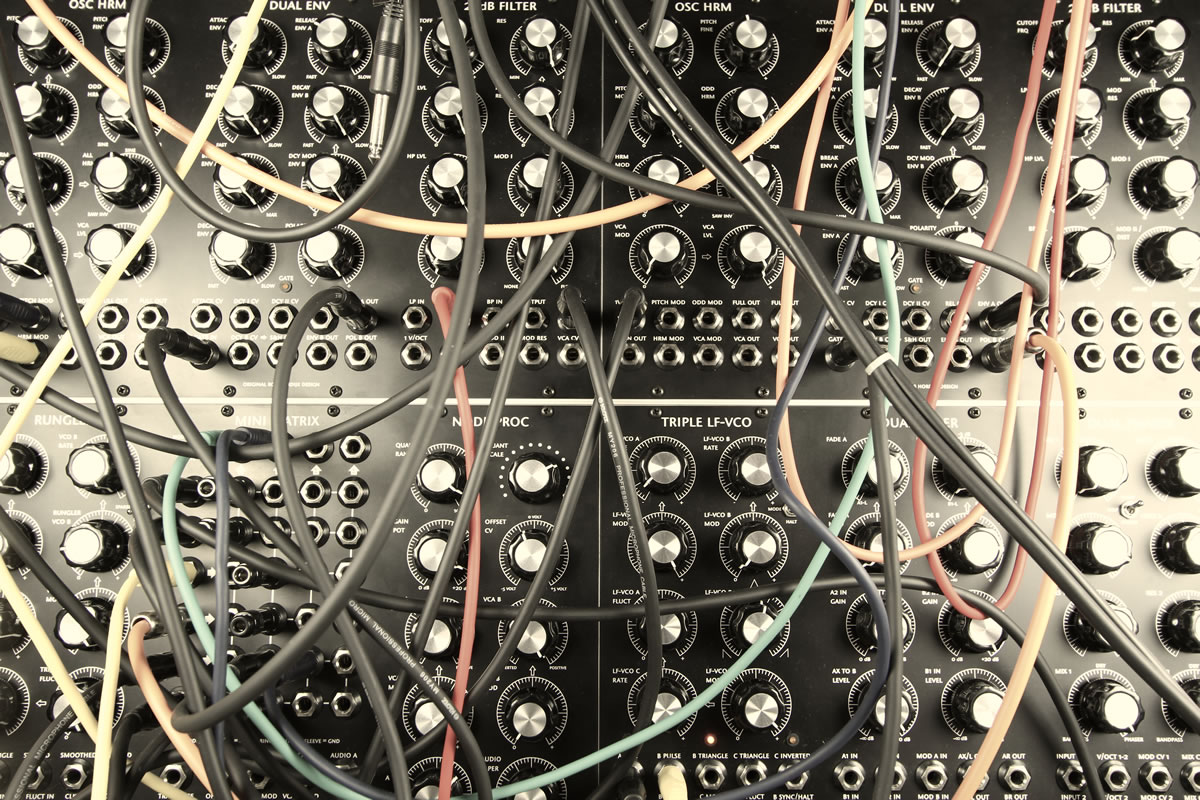
What applies for the design of a complete new instrument also applies in part to building up a synthesizer from commercially available modules. It is important to understand each module as having a specific function within a larger, more complex process. One can make a conceptual design for such a system, with answers to the questions what genre of music one wants to make and what would be needed for that. The ergonomic choices could indicate if one would best go the Eurorack route or the 5MU route, or some other possible route. Then one could make a functional design, listing a well-balanced set of functions that would sufficiently do the required tasks. And then replace the algorithmic layer with a search for the type and brand of modules that meet the functional requirements and the quality level one is after. The final assembly stage would be simple — just get your wallet out and order the chosen modules and fit them in frame.
But for the musician that wants something special and unique and who is willing to do some work, the DIY approach is the most versatile. The author hopes that for those who have this ambition this article has provided some general guidelines that may hopefully help to transform this ambition into some beautiful and unique instruments.
Social top