History of Electronic Sound Modification
Harald Bode first presented his lecture “History of Electronic Sound Modification” in the sound studio at Media Study / Buffalo on September 12, 1979. Other presentations were held at the Experimental Television Center and Binghamton University in 1980, and in 1981 at the Midwest Acoustics Conference (MAC) and the 70th Audio Engineering Society Convention. The presentation included 18 audio tape recordings and 71 slides. Many of the slide diagrams were original, hand-drawn by Harald. Later in 1984, he wrote this shorter text version for publication in the Journal of the Audio Engineering Society 32/10 (October 1984, pp. 730–738). A current project of the Harald Bode Archive is to reconstruct the original lecture with complete audiovisual elements. The following image files are from the original 1981 slides and source photographs from the Harald Bode Archive.
The history of electronic sound modification is as old as the history of electronic musical instruments and electronic sound transmission, recording and reproduction. Means for modifying electrically generated sound have been known since the late 19th century, when Thaddeus Cahill created his Telharmonium (Cahill 1897).
With the advent of the electronic age, spurred first by the invention of the electron tube, and the more recent development of solid-state devices, an astounding variety of sound modifiers have been created for filtering, distorting, equalizing, amplitude and frequency modulating, Doppler effect and ring modulating, compressing, reverberating, repeating, flanging, phasing, pitch changing, chorusing, frequency shifting, analyzing, and resynthesizing natural and artificial sound.
In this paper, some highlights of historical development are reviewed, covering the time from 1896 to the present.
The Electromechanical Era
To give a more complete account on this history, it is important to include the time span that preceded the purely electronic era, and also to include some history of electronic (and electrical) instruments whose sound modification devices formed an integral part of the entire system.
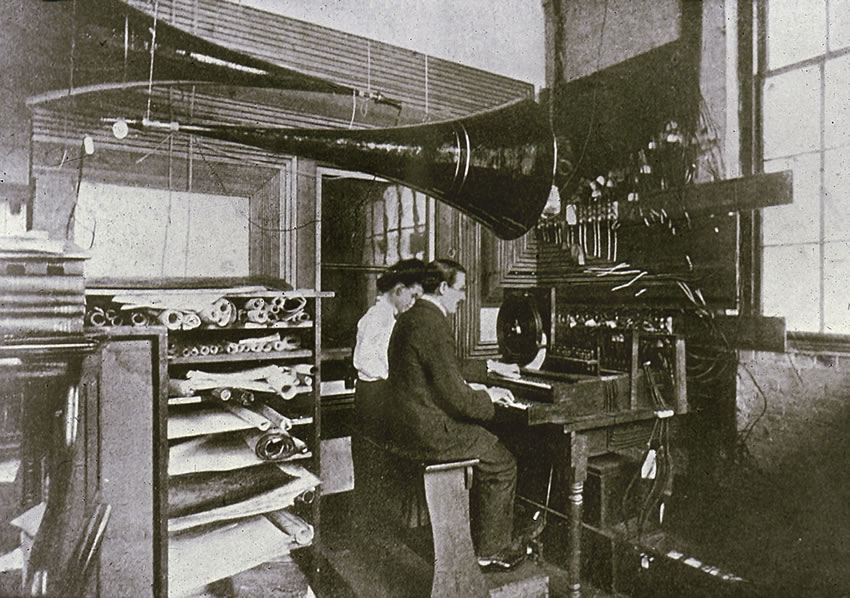
A classic case is the Telharmonium, by Thaddeus Cahill (Fig. 1), which was built around 1896. This instrument used the principle of additive tone synthesis for sound manipulation and modification. The individual tone colours were built up from fundamentals and overtones, generated by huge dynamos. For the purpose of generating pure sine waves for the synthesis, the individual generator coils were tuned with capacitors, another means of sound modification.
The Electronic Era
After the Telharmonium, and especially after the invention of the vacuum tube, scores of electronic (and electronic mechanical) musical instruments were invented with sound modification features. The Hammond organ is of special interest, since it evolved from Cahill’s work. Many notable inventions in electronic sound modification are associated with this instrument, which will be discussed later.
Other instruments of the early 1930s included the Trautonium by the German Friedrich Trautwein, which was built in several versions. The Trautonium used resonance filters to emphasize selective overtone regions, called formants (Sala 1953, 346–348 and Trautwein 1954, a.o.). In contrast, the German Jörg Mager built an organ-like instrument for which he used loudspeakers with all types of driver systems and shapes to obtain different sounds.
In 1937 the author created the Warbo Formant organ, which had circuitry for envelope shaping as well as more complex filters than those used before. It had two sets of filters and a four-voice assignment keyboard (Rhea 1979, 89) through which, for instance, voices 1 and 3 could be assigned to the first filter and voices 2 and 4 to the second filter (Fig. 2). By making the pass regions of the filters mutually exclusive, complementary tone colours could be produced, which sounded very pleasing to the ear (Bode 1940, 67 and 1961, 267).
In the late 1930s, the Hammond Novachord was created, which also had formant filters for overtone modification and envelope shaping to produce tones like those of wind and string instruments (Electronics 1939 and Newsweek 1939, 36).
An interesting means of sound modification is found in the Electrochord by Oscar Vierling (Bode 1940, 67) and in the Miessner piano (Literary Digest 1933, 23; Miessner 1937a and 1937b, 259–272; Rhea 1978, 62). It was found that tonal qualities could be dramatically modified by changing the location of pickups (in this case capacitive) along the strings. For instance, when picking up the oscillations at the midpoint, all even harmonics would disappear, leaving only the odd harmonics, thus producing a hollow, clarinet-like sound. Placing the pickup at one third of the string’s length, the third, sixth and so forth harmonics would be cancelled, and pickup points at other locations of the string length would produce yet different harmonic structures.
The Electrochord as well as the Miessner piano were built without sounding boards, thus eliminating their damping effect and producing tones with longer decay times. The same was true for the Les Paul guitar, and it might be interesting to learn that Paul invented the solid-body guitar as far back as 1927 (Paul 1981). In his early experiments Paul used the magnets of the old-style headphones, which were equipped with steel diaphragms as membranes. The Gibson guitar evolved in 1941, and it has since been associated with an incredible number and variety of sound modification devices and methods, some of which will be discussed in more detail.
From the beginning, one important means of sound modification has been the tremolo and the vibrato, the tremolo being an amplitude modulation (Mroz 1941) and the vibrato a frequency modulation. It is interesting to note that post-source frequency modulation initially posed a problem. For this reason the first Hammond organs were equipped with means for amplitude modulation or tremolo.
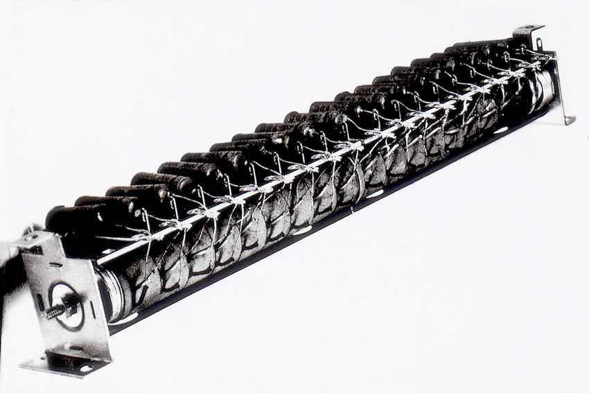
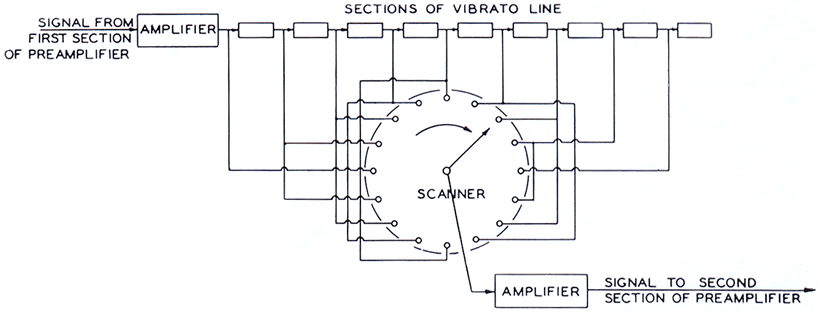
In the mid-1940s, a delay line with variable inductors was invented by Hanert (1945 and 1950b), and after this a different type of variable delay line with a number of delay taps and a capacitive scanner was incorporated in the Hammond organ (Figs. 3 and 4). By combining the direct and frequency-modulated signals, a type of choral effect was produced (Hanert 1950a). This laid the foundation for today’s phasers. In the mid-1950s, W.C. Wayne, Jr., proposed and built a purely electronic choral tone modulator for the Baldwin organ (Wayne Jr. 1961). A different approach for choral tone modulation was taken by Don Bonham in the early 1960s (Bonham 1963), after he had created successfully a purely electronic vibrato modulator in 1958 (Bonham 1961).
A unique contribution in sound modification devices was made by Homer Dudley through his creation of the voder and the vocoder in the late 1930s.
The vocoder was a keyboard-operated instrument controlling a number of band-pass channels for simulating the resonances of the human voice (Dudley 1938). With the addition of a tone source called the buzz source and a noise source called the hiss source, vowels and consonants of a speaker were imitated.
The system became even more exciting when the voder, being an encoder, was combined with a decoder. This combination was called the vocoder, which comprised an analyzer for analyzing the speech and a synthesizer for remaking the same speech (Dudley 1939a, 122–126 and 1939b, 169).
In order to accomplish this, the audio range was sliced up into a number of band-pass channels in the analyzer, which correspond to an equal number of band-pass channels in the synthesizer. In each analyzer channel a control voltage is generated with what we now call an envelope follower. This control voltage was then fed to the control voltage input of a voltage-controlled amplifier in the corresponding synthesizer channel.
Listening to the recordings of the Dudley vocoder, one notices that not only the speech articulation is being remade but also the speech inflection, which clearly indicates the presence of a pitch extractor — that works — as well as a pitch-to-voltage converter and a voltage-controlled oscillator. In the closing section of this article a few more aspects, modifications and applications of the vocoder will be discussed.
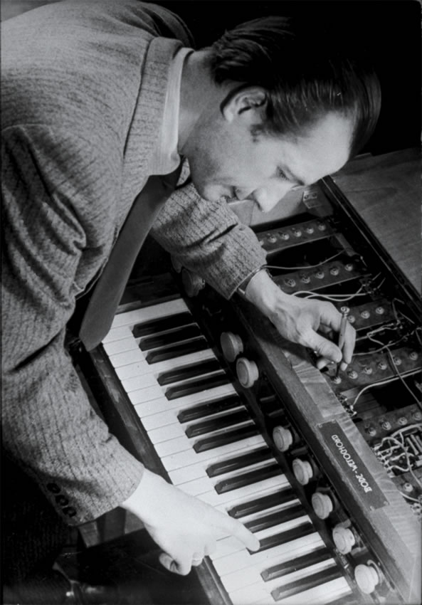
Thus far it has been observed that one important element in sound modification devices is represented by a variety of filters, such as the formant filters of the Trautonium and the Hammond Novachord, the complementary tone filters of the Warbo Formant organ, and the band-pass filters of the vocoder. Another instrument with strong formant filters was the Bode Melochord (preceded by the Melodium) [Rhea 1980a, 68], which was built for several major broadcast stations in West Germany by the late 1940s and the early 1950s. The Melochord (Fig. 5) was also equipped with circuitry for the control of attack and decay envelopes, vibrato and the capability to play travelling formants, the frequency of which was keyboard controlled. In the Melochord built for the Cologne Studio for Electronic Music, the modular concept was adopted, by which external ring modulators, echo chambers and the like could be included in the system (Bode 1954/56, Le Caine 1956 and Meyer-Eppler 1953).
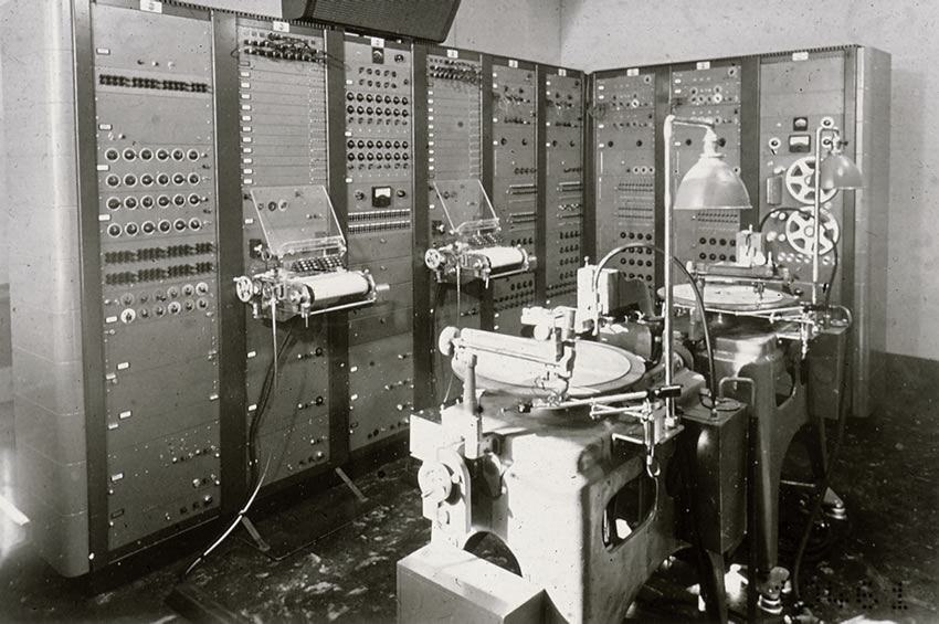
A unique instrument combining many of the means of tone generation and sound modification known at that time was the RCA Synthesizer (Fig. 6), which was created under Harry F. Olson and made its debut in 1955 (Olson and Belar 1953, 595–612, Canby 1956, 64–65 and Babbitt 1964, 251–265). The RCA synthesizer is controlled by pre-programmed punched tape. It has such features as digitally controlled filters, control of attack and decay envelopes, digitally controlled pitch and waveshapes, random noise generation and frequency and amplitude modulation.
Around the same time, Les Paul became famous with his multitrack guitar recordings, using tape speed transposition and the repetition effect. The well-known piece Whispering was done in the early 1950s. Besides being an outstanding performer, Paul is an outstanding innovator. He introduced the multitrack recorder (eight tracks on 1-inch [25 mm] tape) in cooperation with Ampex. He also created Sel Sync. His repetition effect was done with a five-head recorder. His tape speeds were initially 60 and 30 in/s (1.52 and 0.76 m/s), later reduced to 30 and 15 in/s (0.76 and 0.38 m/s). It was Paul who introduced the RIAA curve.
Prior to the tape era, Paul created the repetition effect on 16‑inch (406 mm) disks with five playback pickups in the same groove with the cutting head. This was in 1941.
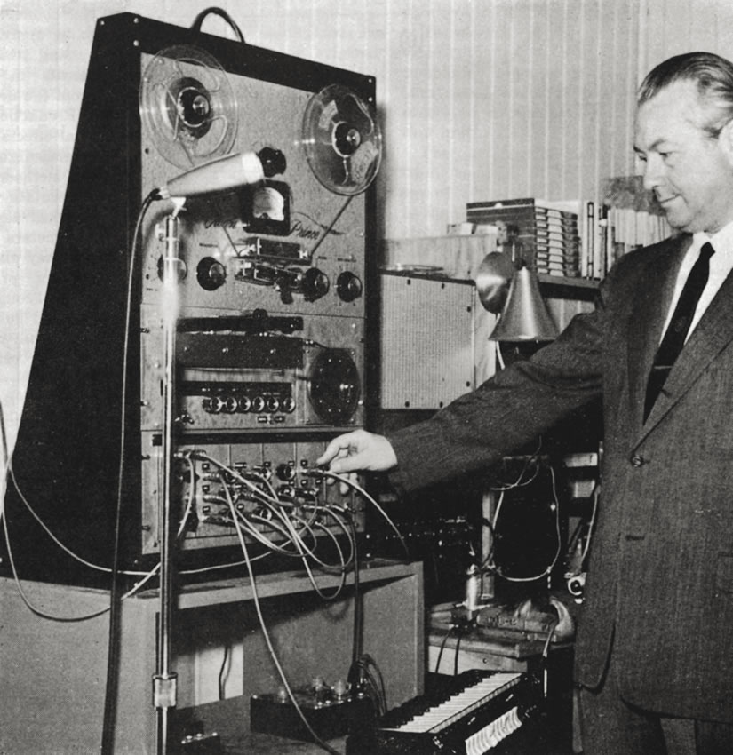
Les Paul of course stimulated many innovators and due to his success encouraged them to work in the field of new sound effects. His influence in many areas is felt to this day. The author was so impressed by his work that he later developed a sound modification system (Fig. 7) consisting of a number of electronic modules, assigned to two separate outputs through a multiple-head tape loop device (Bode 1962). These modules, which will be dealt with in more detail below, also included a ring modulator.
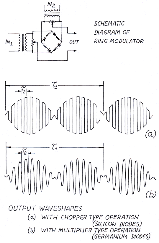
The ring modulator was at the time a relatively little-known sound modification device, mainly used in single-sideband communication systems. The main reason was that up to the mid- or late 1950s it was known as a switching circuit, which would have sounded too harsh to be usable for sound modification. It was only after ring modulators were built with diodes (Fig. 8), which operate in the square law region of their transfer function (as was the case with certain germanium diodes), that they started to perform as four-quadrant multipliers and became musically interesting (Bode 1967 and Oberheim 1970, 334).
The author’s modular sound modification system was built in late 1959 through 1960. In it, the multiplier-type ring modulator and other sound modifying devices were used, such as an envelope follower, a tone-burst responsive envelope generator, a voltage-controlled amplifier, formant and other filters, mixers, a pitch extractor, a comparator and frequency divider for the extracted pitch and a tape loop repeater with dual channel processing (Bode 1961b and 1961a, 264).
The modular concept proved attractive due to its versatility and it was adopted by Robert Moog when he created his modular synthesizer in 1964. This synthesizer included a variety of sound modification devices and system modules, such as voltage-controlled filters (Moog 1965, 260), envelope generators, voltage-controlled amplifiers and sample/hold circuits. At a later date Bode, ring modulators and Bode frequency shifters (which will be described in more detail) were also added to the Moog line.
By the late 1960s, sound effect devices such as the wah-wah appeared in the popular entertainment field. The first successful wah-wah device was reported to have been the Thomas Organ “Cry Baby”, which originated in England around 1965. It worked with germanium transistors. A quite effective wah-wah was, of course, the Moog voltage-controlled low-pass filter, capable of very pronounced resonances which could be actuated by a voltage control pedal. It is understood that the Mutron, an envelope activated voltage-controlled filter, was widely used during the 70s (Milano and Aikin 1979b, 16).
Another popular sound effect device, which started in the mid-1960s, is in the category of the so-called fuzz boxes. The story goes that the fuzz started with Jeff Beck making a guitar recording by overdriving a deficient preamplifier of his tape recorder. The first successful fuzz boxes include the VOX distortion booster, which plugs into a guitar and which originated in England in 1964. At around the same time the Arbiter fuzz face appeared on the scene (Milano and Aikin 1979c, 22). The use of the fuzz effect is quite popular with guitars, and it can be enhanced by extending the sustain time with compression circuits (Anderton 1969, 63–64).
There are, of course, quite a number of other wah-wahs and fuzz boxes on the market, all of which cannot be mentioned within the scope of this publication.
Further electronic sound modification devices that have been successful to this date are flangers and phasers, and it is of interest to trace the history of their discovery and design (Anderton 1978, 9 and Milano and Aikin 1979a, 20).
The flanging effect can be commonly observed outdoors, when a jet flies overhead, and the direct sound is summed in the ear of the observer with the sound reflected from the ground, resulting in the cancellation of certain frequencies and producing the comb filter effect, commonly referred to as “jet sound.”
In the history of recording, the story goes that with the intent to achieve double tracking with two recorders with slightly different speeds on the piece The Big Hurt, the flanging effect was obtained by accident.
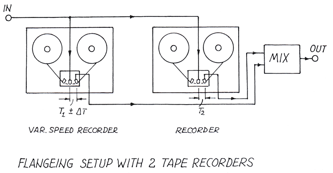
Paul created the flanging effect in Mamie’s Boogie with two disk recorders, one of which had variable speed control (1945). At a later time, with the availability of tape recorders, flanging was done with two tape recorders, one of which had variable speed control (Fig. 9). A famous recording made this way was Itchycoo Park by Small Faces in the late 1960s (Paul 1981).
After the theory of flanging had been established for some time and the industry was waiting for usable integrated circuits to make delay lines of sufficient quality and delay time (Blesser and Lee 1971, 393–397), Richard Factor of Eventide demonstrated electronic flanging with a practically “continuously” variable digital delay line at the Spring Convention of the Audio Engineering Society in 1973 (Factor and Katz 1972, 18). Prior to that, Eventide had been experimenting with bucket brigade devices for several years (Hinkle 1964, 110 and Buss 1977, 55).
The Eventide Instant Flanger was introduced in the spring of 1975. It was later followed by the pitch change module for the 1745M Digital Delay Line and then by the model H910 Harmonizer, which was the first usable transposing device.
In contrast to the work of Factor of Eventide, Steven St. Croix of Marshall Electronic concentrated on the flexibilities of a modulated delay line, which he called the time modulator and for which new analogue delay integrated circuits were developed. With this time modulator a large variety of effects were introduced, such as automatic double tracking, automatic triple tracking, negative flange, positive flange, resonant flange, “negative killer flange,” positive killer flange,” vibrato, arpeggio, pitch quantizing, two-drum slaps, reverb with detune and others. The Marshall time modulator was introduced to the trade in 1976.
Generally speaking, in flangers, a comb filter effect is produced where the spacing of the peaks and notches equals the reciprocal of the delay time. In contrast, in phasers, depending upon the design parameters used for the phase filter, the spacing of the peaks and notches can be made to cover equal musical intervals (Bartlett 1970, 674–675). All-pass phase filters have been known for analogue computers roughly since the 1940s. So basically the technology would have been available to build phasers at that time. According to one report the first user of phasers was Dodie Fields in the mid-1950s. The Countryman phase shifter became known in the early 1970s. One of the successful phasers of the early times was the Maestro phaser, designed by Tom Oberheim.
On the Moog 12-stage phaser the number of phasing stages as well as the number of stages included in the feedback loop could be selected. The Bode Barberpole phaser (introduced in 1981) is capable of unidirectional (infinite) movement of the comb filter peaks and notches.
A very important ingredient in sound modification is the addition of reverberation to program material. In the old days, that is, in the 1930s, one used echo chambers for this purpose, and with very good results. But they were expensive and space consuming. Then in 1941 came the invention of the Hammond spring reverberation device, which was incorporated in his organ tone cabinet (Hammond 1939). It also worked well in studios, and its offspring are still popular. A different approach for producing reverberation effects was taken by D.W. Martin of the Baldwin Piano Company, who used coil springs, which were mechanically coupled with the loudspeaker cone (Martin and Knoblaugh 1954, 674–675).
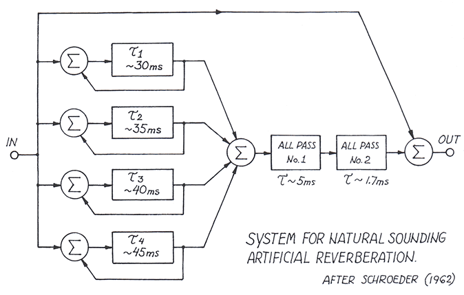
Another way to produce reverberation effects successfully is, of course, with tape repeaters. After the advent of useful delay lines artificial reverberation became feasible with tapped delay lines. Schroeder of Bell Laboratories proposed a system for natural reverberation, incorporating a number of delay lines and feedback configurations (Fig. 10) [Schroeder and Logan 1961, 192 and Schroeder 1962, 219]. One of the most successful reverberation devices still in use today is the EMT plate reverberation device.
As was mentioned before, post-source frequency modulation is very important to enhance certain program material. The most famous device to produce Doppler effect vibrato by rotating loudspeakers was and is the Leslie tone cabinet. A purely electronic system for simulating moving sound sources was described by John Chowning in 1971, who proposed the use of all of the required parameters, including amplitude modulation, frequency modulation, and reverberation in four independent channels to achieve this and other moving sound effects (Chowning 1971, 2–6). Prior to this a system for “monaural-binaural transmission of sound for producing a Haas effect” had been proposed by Daniel Martin in 1959.
Different and still relatively little-known sound modification devices are frequency shifters, which are capable of producing quite startling effects. The first frequency shifters were introduced in the 1950s by Heck and Buerck in West Germany (1956, 1). They operated on the principle of heterodyning the program material, for instance through a 20 kHz carrier into a higher frequency range passing one of the sidebands produced through a single-sideband filter (for instance, passing 20 kHz to 30 kHz) and reheterodyning these frequencies back into the audio range with a carrier that deviated from the first (20 kHz) carrier by the amount of frequency shift ultimately desired (Bode 1966, 66).
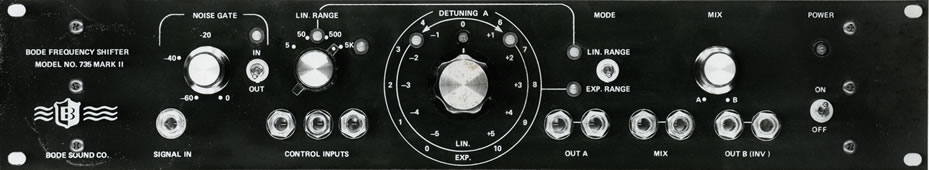
A different variety of frequency shifters now successfully in use operates on the phase shifter and multiplier principle (Bode 1976 and Rhea 1980b, 86). A dual-phase shifter modifies the program signal to produce output signals, which are in 90-degree phase relationship relative to each other over a range from 20 Hz to 20 kHz. These feed into the first inputs of two multipliers. A quadrature oscillator produces sine/cosine-related shift frequencies, which are fed to the second inputs of the two multipliers. The multiplier output signals are typically those of ring modulators. Due to their phase relationships one of the sidebands is suppressed when they are summed in the output circuit, and the other is doubled in amplitude, thus producing a frequency-shifted signal.
Frequency shifters can be used for a variety of interesting effects, including the spiralling echo effect, which is obtained by placing this sound modifier in the feedback loop of a delay circuit (or tape delay). In cooperation with Robert Moog a special model was created in 1973 (Bode and Moog 1972, 453–458 and Bode 1974), which has an exponential control voltage to amount-of-shift interface, so it has a keyboard tracking capability. This means that unusual timbres set up with the frequency shifter can be maintained over the entire keyboard range.
In the 1973 model a beat frequency quadrature oscillator was used, which was later replaced by a wide-range quadrature oscillator (0.02 Hz to 5000 Hz) to improve the frequency stability (Fig. 11) [Bode 1979a].
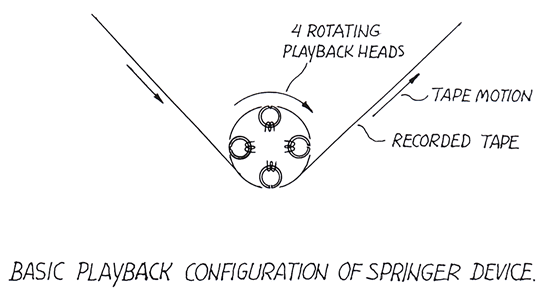
A different category of sound modifiers is that of detuning devices. The harmonizer by Eventide already has been mentioned. Other products of this kind are manufactured by Lexicon and MXR to name just a few. The basic principle of these transposers was first demonstrated in the late 1940s on the Springer apparatus, a machine with multiple rotating tape heads, which is attached to a standard tape recorder.
Another sound modifier of the electromechanical category is the Phonogen, which has a circular arrangement of 12 capstans to change the tape speed within the 12 steps of the tempered scale.
The pitch-transposing idea first executed by Springer has stayed the same in today’s transposing devices, and the basic concept is that of slicing up the program material into a series of splices of sufficiently short duration and to compress or expand these slices before recombining them (Fig. 12).
In contrast to using the slicing method for pitch transposition, where smooth transition is a main objective, it can also be applied for the opposite purpose, namely, to change the sound with each new slice. For achieving this effect, the sample/hold method is applied by assigning different sound parameters (for instance, different filter frequencies) to each segment.
As mentioned before, filtering represents a very basic method of sound modification. A unique kind of filter worth mentioning is the string filter by Moog, comprising four groups of nine very selective filters which can be activated in different configurations for strongly accentuated tone colourings, including those of strings. When all filters are activated, a total of 36 resonators cover the performance range.
Finally, in closing, a few more details relating to vocoders will be discussed.
Long before Dudley’s vocoder became known, there was an electromechanical driver unit known as Sonovox, which imparted vibrations in the range of voice frequencies to the vocal cavity system when held against the area of the larynx, thus substituting for the vocal cords and making” semi-synthesized” speech possible. This in a sense was the forerunner of the artificial larynx still in use today. Another interesting device, which preceded today’s vocoders, was called “the bag,” with the name of Bob Heil associated with it (Anderton 1983, 98). It could be nicknamed “the poor man’s vocoder.” It consisted of a loudspeaker driver system with a vinyl tube from this driver feeding into the mouth of the performer, who then spoke vowels with the frequencies supplied by the driver into a microphone. Although very effective on vowels, the use of this device was quite limited for intelligible speech.
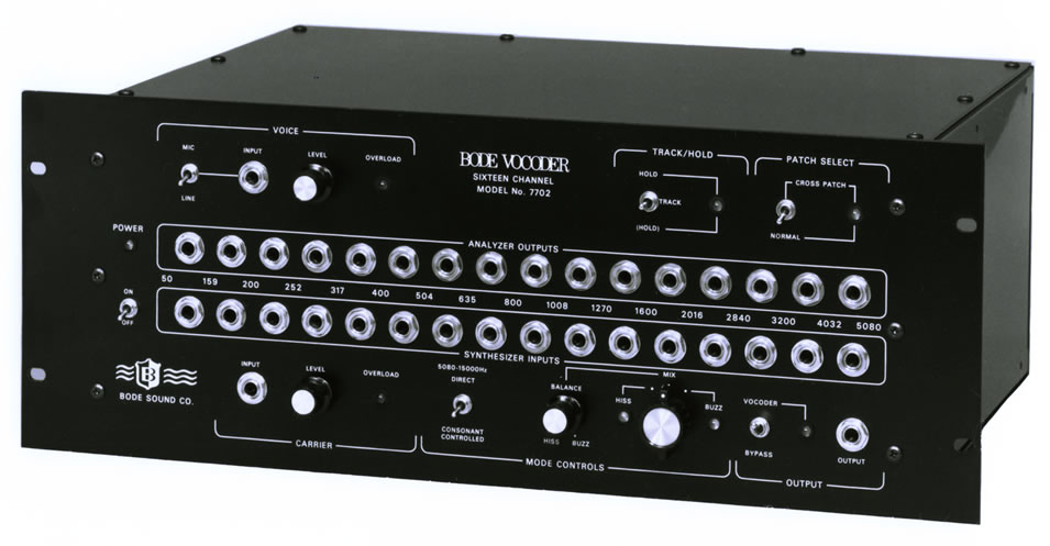
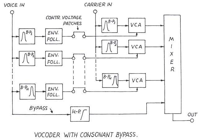
After Dudley, Robert Moog was the first designer of a vocoder using semiconductor technology and active filters. It was built for the electronic music studio of the University of Buffalo in 1968. After that other vocoders followed. Those by Sennheiser and EMS (Condron and Ford 1977, 98; Moog 1978, 54) became known in the late 1970s. In 1977, the author developed a vocoder that deviated from the classical communication-type concept employed by Dudley and others and was aimed toward the use of direct performance (and entertainment) applications (Fig. 13). This model features a direct bypass for the consonant frequencies since it was evident that only the vowel frequencies had to be encoded and decoded and not the consonants, which did not have to change anyway. This system, which was patented in 1979, resulted in an instrument of superior intelligibility, presence, and fast response (Fig. 14). After these vocoders a number of other products in this category appeared on the scene, such as the Korg, the Electroharmonix, the Syntovox and the Roland, all of which use the conventional approach.
Closing Remarks
It was the purpose of this presentation to highlight those developments in the field of electronic sound modification that were deemed to be most basic and significant. It will have been observed that some of the principles used today can be traced back to the very early days of experimentation and that many of them have survived all phases of the technological evolution.
Acknowledgments
The author wishes to express his appreciation to those who have supported this work. His special thanks go to Dave Luce and Tom Rhea for their help in providing the documentation.
Bibliography
Anderton, Craig. “For Your Guitar, a Compression Sustainer.” Popular Electronics 30 (May 1969).
_____. “Sound Modification Devices for Keyboards: An Introduction.” Contemporary Keyboard (July 1978).
_____. Guitar Gadgets. New York NY: Amsco Publications, 1983.
Babbitt, Milton. “An Introduction to the RCA Synthesizer.” Journal of Music Theory 8/2 (Winter 1964).
Bartlett, Bruce. “Letters to the Editor: A Scientific Explanation of Phasing (Flanging).” Journal of the Audio Engineering Society 18/6 (December 1970).
Blesser, Barry A. and Francis F. Lee. “An Audio Delay System Using Digital Technology.” Journal of the Audio Engineering Society 19/5 (May 1971).
Bode, Harald. “Bekannte und neue Klänge durch elektrische Musikinstrumente.” Funktechnische Monatsheft 5 (1940).
_____. “The Melochord of the Cologne Studio for Electronic Music.” Technical Trans. (TT-607) of “Das Melochord des Studios für elektronische Musik im Funkhaus Köln,” in Technische Hausmitteilungen des Nordwestdeutschen Rundfunks 6/1–2, Sonderheft über elektronische Musik (1954). Ottawa: National Research Council of Canada, 1956.
_____. “European Electronic Music Instrument Design.” Journal of the Audio Engineering Society 9 (October 1961).
_____. “Electronic Apparatus” (Modular Sound Modification System with Tape Repeater). Patent US 3,069,956 (filed 21 April 1960, patented 25 December 1962). http://ip.com/patent/US3069956
_____. “A New Tool for the Exploration of Unknown Electronic Music Instrument Performances.” Journal of the Audio Engineering Society 9 (October 1961).
_____. “Sound Synthesizer Creates New Musical Effects.” Electronics (1 December 1961). Republished in eContact! 13.4 — Harald Bode Archive (July 2011). https://econtact.ca/13_4/bode_synthesizer.html
_____. “Solid State Audio Frequency Spectrum Shifter.” Journal of the Audio Engineering Society 14/1 (January 1966). Proceedings of the 17th Convention of the Audio Engineering Society (October 1965).
_____. “The Multiplier Type Ring Modulator.” Electronic Music Review 1 (1967).
_____. “Apparatus for Producing Special Audio Effects Utilizing Phase Shifting Techniques (BFO Frequency Shifter).” Patent US 3,800,088 (filed 28 August 1972, patented 26 March 1974). http://ip.com/patent/US3800088
_____. “Frequency Shifters for Professionals.” db Magazine (March 1976).
_____. “Multiphase Signal Oscillator” (Quadrature Oscillator for Frequency Shifter). Patent US 4,145,670 (filed 5 July 1977, patented 20 March 1979). http://ip.com/patent/US4145670
_____. “Analog Speech Encoder and Decoder (Bode Vocoder).” Patent US 4,158,751 (filed 6 February 1978, patented 19 June 1979). http://ip.com/patent/US4158751
Bode, Harald and Robert A. Moog, “A High-Accuracy Frequency Shifter for Professional Audio Applications.” Journal of the Audio Engineering Society 20 (July/August 1972).
Bonham, Don L. “Vibrato Circuit Comprising a Bridge Having Non-Linear Impedance Elements.” Patent US 2,988,706 (filed 29 October 1958, patented 13 June 1961). http://ip.com/patent/US2988706
_____. “Electrical Music System” (Choral Tone Modulator).” Patent US 3,083,606 (filed 2 March 1959, patented 2 April 1963). http://ip.com/patent/US3083606
Boyle, Williard S. and George E. Smith. “Charge Coupled Semiconductor Devices.” Bell System Technical Journal 49 (April 1970), pp. 587–593.
Buss, R. “CCD’s Improve Audio Systems Performance and Generate Effects.” EDN (5 January 1977).
Cahill, Thaddeus. “Art of and Apparatus for Generating and Distributing Music Electrically.” Patent US 580,035 (filed in 1896, patented 6 April 1897). http://ip.com/patent/US580035
_____. “The Cahill Telharmonium.” Electrical World (1906).
_____. “The Generating and Distributing of Music by Means of AC Generators.” Electrical World (1906), p. 519.
_____. “Music by Electricity.” M. Melius World’s Week 12 (June 1906), pp. 7660–7663.
_____. [?] “The Telharmonium: An Apparatus for the Electric Generation and Transmission of Music.” Scientific American 96 (9 March 1907), pp. 205, 210–221.
Canby, E.T. “Music Synthesizer (RCA SYN).” Audio 40 (May 1956).
Chowning, John M. “The Simulation of Moving Sound Sources.” Journal of the Audio Engineering Society 19/1 (January 1971).
Condron, Nik and Hugh Ford. “EMS Vocoder.” Studio Sound (July 1977).
Contemporary Keyboard staff. “Effects Devices Part 1: Phasers and Flangers.” Contemporary Keyboard (February 1979).
_____. “Effects Devices Part 2: Volume and Wah-Wah Pedals.” Contemporary Keyboard (April 1979).
_____. “Effects Devices Part 3: Envelope Followers, Noise Gates and Fuzz Tones.” Contemporary Keyboard (June 1979).
Dudley, Homer W. “System for the Artificial Production of Vocal or Other Sounds” (Voder). Patent US 2,121,142 (filed 7 April 1937, patented 21 June 1938). http://ip.com/patent/US2121142
_____. “The Vocoder.” Bell Labs Record 17 (1939).
_____. “The Vocoder.” Journal of the Acoustical Society of America 11/2 (1939).
Electronics. “Novachord.” Electronics (November 1939).
Factor, Richard and Stephen Katz. “The Digital Audio Delay Line.” db Magazine (May 1972).
Gensmer, Harald. “Das Mixtur-Trautonium.” Musikleben 7 (July/August 1954), pp. 245–247.
Greiser, W. “Das Mixtur-Trautonium.” Musica 12 (May 1958), pp. 307–308.
Hammond, Laurens. “Electrical Musical Instrument” (Coil Spring Reverberation). US Patent 2,230,836 PAPERS (filed 15 July 1939, patented 4 February 1941).
Hanert, John M. “Electrical Musical Apparatus” (L-C Delay Line with Variable Inductors for Post-Source Vibrato Modulation). Patent US 2,382,413 (filed 10 May 1943, patented 14 August 1945). http://ip.com/patent/US2382413
Hanert, John M. “Electrical Musical Instrument.” Patent US 2,498,367 (filed 15 September 1944, patented 21 February 1950). http://ip.com/patent/US2498367
_____. “Electrical Musical Apparatus.” Patent US 2,509,923 (filed 8 March 1946, patented 30 May 1950). http://ip.com/patent/US2509923
Heck, L. and F. Buerck. “Klangumformungen in der Rundfunkstudiotechnik, insbesondere durch Anwendung der Frequenzumsetzung.” Elektronische Rundschau [10/1] (January 1956).
Hinkle, F. “Bucket Brigade Shift Register Generates Constant Phase Delay.” Electronics (11 July 1964).
Le Caine, Hugh. “Electronic Music.” Proceedings of the IRE — Institute of Radio Engineers 44/4 (April 1956). [Includes a description of the Bode Melochord of Studio for Electronic Music at Cologne.]
Literary Digest. “Piano with a Whole Band in It: B.F. Miessner’s Electronic Piano.” The Literary Digest 115 (25 March 1933).
Martin, Daniel W. “Monaural-Binaural Transmission of Sound for Producing a Haas effect.” Patent US 2,879,683 (filed 31 December 1956, patented 31 March 1959). http://ip.com/patent/US2879683
Martin, Daniel W. and Armand F. Knoblaugh. “Loudspeaker Accessory for the Production of Reverberant Sound.” Journal of the Acoustical Society of America 26/5 (September 1954). [Coil springs mechanically coupled with speaker cone.]
Meyer-Eppler, Werner. “Which Possibilities Exist for the Meaningful Application of Electronic Music Instruments?” in Electro-acoustics. Proceedings of the 1st ICA — International Congress on Acoustics (Delft, 1953). [Features the Bode Melochord of the Cologne Electronic Music Studio.]
Miessner, Benjamin Franklin. “Electronic Piano Produced Commercially.” Electronics (November 1937).
_____. “The Electronic Piano.” Proceedings of the Music Teachers National Association (1937).
Moog, Robert A. “Voltage-Controlled Low-Pass High-Pass Filter for Audio Signal Processing.” Journal of the Audio Engineering Society 13/3 (July 1965). Preprint #413 of the Proceedings of the 17th Convention of the Audio Engineering Society (October 1965).
_____. “Vocal Sounds, Part II: Vocoders.” Contemporary Keyboard (May 1978).
Mroz, Matthew Z. “Electrical Musical Instrument (Electro-Mechanical Tremolo Circuit).” Patent US 2,245,354 (filed 8 December 1938, patented 10 June 1941). http://ip.com/patent/US2245354
Newsweek. “Pianoless Piano: Hammond Electrical Novachord Mystifies Musicians.” Newsweek 13 (20 February 1939).
Oberheim, Thomas E. “A ‘Ring Modulator’ Device for the Performing Musician.” Proceedings of the 38th Convention of the Audio Engineering Society (May 1970).
Olson, Harry F. and Herbert Belar. “Electronic Music Synthesizer.” Journal of the Acoustical Society of America 27 (May 1955).
Paul, Les. Personal interview. Spring 1981.
Peterson, Edward. “The Rich History of the Electronic Organ.” Keyboard (November 1983), pp. 32–36.
Rhea, Thomas L. “Electronic Perspectives: The Cahill Telharmonium, Part I.” Contemporary Keyboard 3 (February 1977), p. 47.
_____. “Electronic Perspectives: The Cahill Telharmonium, Part II.” Contemporary Keyboard 3 (March 1977), p. 55.
_____. “Electronic Perspectives: Benjamin Franklin Miessner’s ‘Stringless Piano’.” Contemporary Keyboard (April 1978).
_____. “Electronic Perspectives: Harald Bode’s Four Voice Assignment Keyboard (1937).” Contemporary Keyboard (December 1979). Republished in eContact! 13.4 — Harald Bode Archive (July 2011). https://econtact.ca/13_4/rhea_bode_warbo.html
_____. “Electronic Perspectives: Bode’s Melodium and Melochord.” Contemporary Keyboard (January 1980),. Republished in eContact! 13.4 — Harald Bode Archive (July 2011). https://econtact.ca/13_4/rhea_bode_melodium.html
_____. “Electronic Perspectives: Harald Bode’s Frequency Shifters and Vocoders.” Contemporary Keyboard (February 1980). Republished in eContact! 13.4 — Harald Bode Archive (July 2011). https://econtact.ca/13_4/rhea_bode_vocoder.html
Sala, Oskar. “Das neue Mixtur-Trautonium.” Musikleben 6 (October 1953).
Schroeder, Manfred R. “Natural Sounding Artificial Reverberation.” Journal of the Audio Engineering Society 10/3 (July 1962).
Schroeder, Manfred R. and Benjamin F. Logan. “‘Colorless’ Artificial Reverberation.” Journal of the Audio Engineering Society 9/3 (July 1961).
Trautwein, Friedrich. “The Electronic Monochord.” Technical Trans. of “Das elektronische Monochord,” in Technische Hausmitteilungen des Nordwestdeutschen Rundfunks 6/1–2, Sonderheft über elektronische Musik (1954). Ottawa: National Research Council of Canada, 1956.
Wayne Jr., William C. “Audio Modulation System” (Choral Tone Modulator). Patent US 3,004,460 (filed 31 December 1956, patented 17 October 1961). http://ip.com/patent/US3004460
Woodland, W.C. “Musical Problem Solved by the Telharmonium.” Scientific American 96 (30 March 1907), p. 271.
Social top